2. Computer aided design#
This week, we worked on 2D/3D modelisation by using CAD.
We were introduced to a load of software (opensource) and we were asked to chose one.
These software will allow us to develop images and then we can even print them out if wanted.
The ones I used were Inkscape and OPENSCAD
Compliant and bistable mechanisms#
The first question is what a compliant mechanism is ❓
It’s as a flexible mechanism which means that it has a flexible body and by flexing it, it’s able to achieve force and motion tranmission (works like a string).
The second question you must be asking yourself is what is a bistable mechanism then ❓
Well it’s a mechanism that has two stable equilibrium positions.
It’s nice bc it has the ability to stay in two positions without any input and despite small external disturbances.
Inkscape#
Before coming to the first lesson of the week, I’d had already install Inkscape, which is a 2D modelisation software of most commonly known as a virtual drawing software.
You can follow this link to download the software and this tutorial could really help you if you haven’t had the basics before.
OPENSCAD#
We were given a tutorial to follow if needed: tuto
OPENSCAD is only used with code so you will have to learn the language!
Here is a cheatsheet that could be useful <3
Some syntax that I’ve used:
| Command | Description |
|---|---|
union |
allows to join 2 pieces together |
hull |
makes things round and connect them |
difference |
allows to substract one piece from another |
rotation |
rotate an object |
resize |
resize an object |
sphere(r/d) |
make a sphere |
cylinder(h,r/d,center) |
make a cylinder |
$t |
live animation |
My project#
Let’s be honest, I hate C++ and this language really don’t come easy for me so I chose a project that I felt like I would be able to make come to reality in the end.
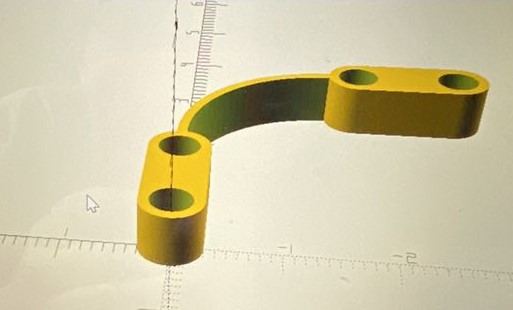
I decided to make a fixed-fixed beam quarter circle
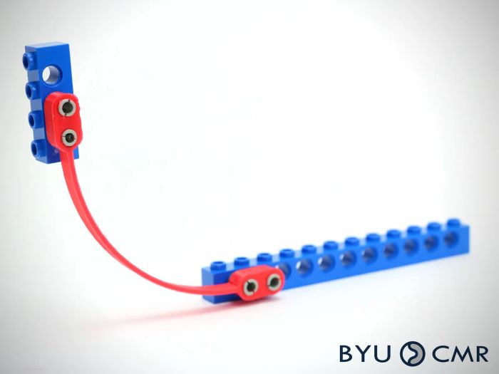
With Eliott and Emilie, we’ve had the idea to make a catapult by joining our 3 pieces :))
This was the first design:
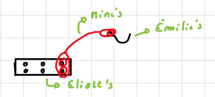
Eliott is gonna make a lego brick and Emilie is gonna make the round part of the catapult.
Because we’re joining our pieces, it’s very important that we parameter our prototypes so that they can perfectly fit together.
Final code#
This is my final code for my prototype.
Next week, I’ll be able to print it 😎
// File : final product.scad
//Author : Camille Lamon
// Date : 10/10/2023
// License : Creative Commons Attribution-ShareAlike 4.0 International [CC BY-SA 4.0](https://creativecommons.org/licenses/by-sa/4.0/)
$fn = 100;  // define resolution of the circle

width = 0.6;  // width of the structure.
thickness = 0.6;  // thickness of the structure.
rad_ext = width / 2;  // Exterior radius of the cylinder.
diff = 0.1;  // space between the hole and the structure
rand = 0.01;  // random number for the imperfections
rad_s = 1.5;  // Radius of the upper holes.
width_s = 0.1;  // width of the upper holes
n_holes = 2;  // Number of holes
holes_gap = 1.5;  // gap between holes

union() {
    // "difference" is going to help me make the main beam with aligned holes
    difference() {
        // "union" to create the central part of the structure.
        union() {
            cylinder(thickness, rad_ext, rad_ext);  // makes a cylinder.
            translate([0, -rad_ext, 0])
            cube([holes_gap * (n_holes - 1), width, thickness]);  // makes a space for the aligned holes
            translate([holes_gap * (n_holes - 1), 0, 0])
            cylinder(thickness, rad_ext, rad_ext);  // makes another cylinder.
        }
        // "union" to create the aligned holes
        union() {
            for (i = [0:n_holes-1]) {
                translate([holes_gap * i, width / 2, (thickness + rand) / 2])
                rotate([90, 0, 0])
                cylinder(thickness + rand, rad_ext - diff, rad_ext - diff);  // makes the holes
            }
        }
    }
    // "Translation"+ "difference" to make an upper hole
    translate([holes_gap * (n_holes - 1) + rad_ext, -rad_s + width_s / 2, 0])
    difference() {
        cylinder(thickness, rad_s, rad_s);
        translate([0, 0, -rand / 2])
        cylinder(thickness + rand, rad_s - width_s, rad_s - width_s);
        translate([-rad_s, -rad_s, -rand / 2])
        cube([rad_s, rad_s * 2, thickness + rand]);
        translate([-rand / 2, -rad_s, -rand / 2])
        cube([rad_s + rand, rad_s, thickness + rand]);
    }
    translate([holes_gap * (n_holes - 1) + rad_ext + rad_s - width_s / 2, -rad_s - (holes_gap * (n_holes - 1) + rad_ext) + width_s / 2, 0])
    difference() {
        // "union" to male the upper beam
        union() {
            cylinder(thickness, rad_ext, rad_ext);  // makes a cylinder
            translate([-rad_ext, 0, 0])
            cube([width, holes_gap * (n_holes - 1), thickness]);  // makes a space for the aligned holes
            translate([0, holes_gap * (n_holes - 1), 0])
            cylinder(thickness, rad_ext, rad_ext);  // makes another cylinder
        }
        // "union" makes the aligned holes in the upper beam
        union() {
            for (i = [0:n_holes-1]) {
                translate([-width/2, holes_gap * i, (thickness + rand) / 2])
                rotate([0, 90, 0])
                cylinder(thickness + rand, rad_ext - diff, rad_ext - diff);  // makes the holes
            }
        }
    }
}
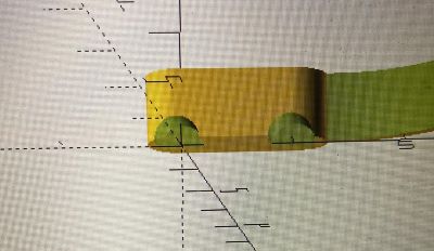
The prototype looks like this in 3D visualisation:
And also like this, if you want to take your time to look at it:
Problems that occured#
Previously, I’ve shown you my final code but I’m gonna be honest and tell you that I STRUGGLED a lot to get to the final product so I’m going to get you through all of my fails before finding the ultimate code so that you don’t make the same mistakes.
At first, my structure looked like this and the problem I had was that my holes were not orientated in the way I needed so I had to rotate them.
So it used to look like this:
When i was finally able to rotate them, another problem appeared…The holes were not centered
That’s went I asked for help because I really didn’t understand wtf was going on 😧
The explaination i was given was that when I rotated by 90°, my holes extended in both directions from the center so I had to adjust my translation and write:
union(){
    for (i=[0:n_holes-1]){
        translate([holes_gap*i, width/2, (thickness + rand)/2])
        rotate([90,0,0])
        cylinder(thickness+rand, rad_ext-diff, rad_ext-diff);
At that point, I had finally adjusted my holes in the center upper beam but I still hadn’t changed anything on the lower upper beam.
I did the same translation change to have the holes centered but I only saw one hole and I had no idea why 😡
I have a strip length holes_gap * (n_holes - 1) and I place each hole at holes_gap*i along this strip.
So the problem is that holes_gap * (n_holes - 1) doesn’t create a long enough strip for all the holes if I start my loop at i = 0
I modified my loop by writing:
translate([holes_gap*(n_holes-1)+rad_ext+rad_s-width_s/2,-rad_s-(holes_gap*(n_holes-1)+rad_ext)+width_s/2,0])
difference(){
    union(){
        cylinder(thickness, rad_ext, rad_ext);
        translate([-rad_ext, 0, 0])
        cube([width, holes_gap * (n_holes - 1), thickness]);
        translate([0, holes_gap * (n_holes - 1), 0])
        cylinder(thickness, rad_ext, rad_ext);
    }
    union(){
        for (i=[0:n_holes-1]){
            translate([0, i * holes_gap, (thickness + rand) / 2])
            rotate([0, 90, 0])
            cylinder(thickness+rand, rad_ext-diff, rad_ext-diff);
        }
    }
}
And the final problem was that the holes were not completely going through and it was because in my translation, I wrote 0 and I had to change it for -width/2:
(translate([-width/2, holes_gap * i, (thickness + rand) / 2]))
As you may have understood, this module took a lot of time for me as I got stuck several times 😬
Licenses#
I decided to use the license CC BY-SA which:
allows reusers to distribute, remix, adapt, and build upon the material in any medium or format, so long as attribution is given to the creator. The license allows for commercial use. If you remix, adapt, or build upon the material, you must license the modified material under identical terms. CC BY-SA includes the following elements: BY – Credit must be given to the creator. SA – Adaptations must be shared under the same terms.
// File : final product.scad

//Author : Camille Lamon

// Date : 10/10/2023

// License : Creative Commons Attribution-ShareAlike 4.0 International [CC BY-SA 4.0](https://creativecommons.org/licenses/by-sa/4.0/)
Here is a table of license if you need:
| abbreviation | description |
|---|---|
| CC | Means that it has a Creative Commons license |
| BY | Credits must be given to the author |
| SA | Adaptations must be shared under the same terms |
| NC | Not allowed to commercialize it |
| ND | No adaptations of the work allowed |
| CC0 | Their work become public domain |
Checklist#
- Parametrically modelled some FlexLinks using 3D CAD software
- Shown how you did it with words/images screenshots
- Included your original design files
- Included the CC license to your work
- Documented how you used other people's work and gave proper credit to complete your kit